学习使用IIS芯片驱动音频。
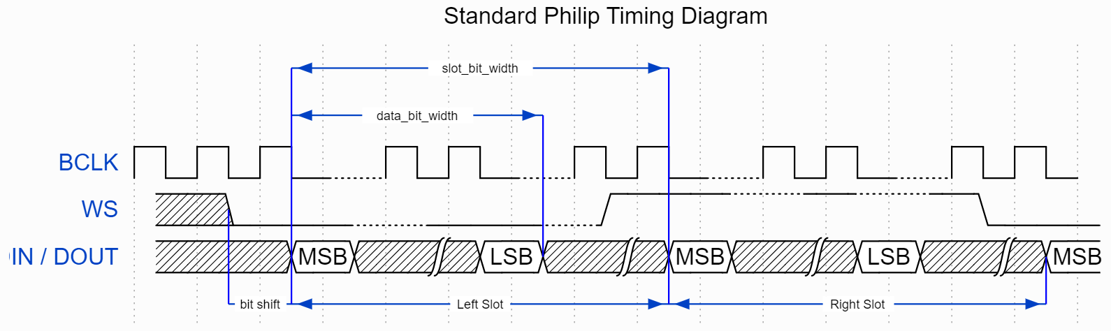
1.IIS各个引脚接口的作用是什么,如何使用IO口模拟IIS接口-初始化代码长啥样? IIS总线,最简就是三条线:
由MCU向I2S解码芯片传数据并播放,加上GND VCC一共五条线。
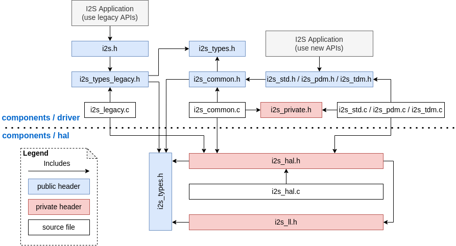
I2S在STM32中不适用,不过在ESP32中用到比较多。ESP32无论是基于ESP-IDF架构的工程还是基于arduino的工程,使用的I2S驱动头文件都是<driver/i2s.h>
i2s.h: The header file of legacy I2S APIs (for apps using legacy driver).
i2s_std.h: The header file that provides standard communication mode specific APIs (for apps using new driver with standard mode).
i2s_pdm.h: The header file that provides PDM communication mode specific APIs (for apps using new driver with PDM mode).
i2s_tdm.h: The header file that provides TDM communication mode specific APIs (for apps using new drivers with TDM mode).
在i2s.h中使用的是最常见的总线协议初始化方式:封装好一个结构体,然后给出结构体参数配饰,再允许初始化函数;使用时会有类似于start者或write 函数运行。
1
2
3
4
5
6
7
8
9
10
11
12
13
14
typedef struct {int mck_io_num; int bck_io_num; int ws_io_num; int data_out_num; int data_in_num; i2s_pin_config_t ; i2s_driver_config_t ; i2s_port_t ;
一些最基础的函数:
1
2
3
4
5
6
7
8
9
10
11
12
13
14
15
16
17
18
19
20
21
esp_err_t i2s_set_pin (i2s_port_t i2s_num, const i2s_pin_config_t *pin) esp_err_t i2s_driver_install (i2s_port_t i2s_num, const i2s_config_t *i2s_config, int queue_size, void *i2s_queue) esp_err_t i2s_driver_uninstall (i2s_port_t i2s_num) esp_err_t i2s_write (i2s_port_t i2s_num, const void *src, size_t size, size_t *bytes_written, TickType_t ticks_to_wait) esp_err_t i2s_write_expand (i2s_port_t i2s_num, const void *src, size_t size, size_t src_bits, size_t aim_bits, size_t *bytes_written, TickType_t ticks_to_wait) esp_err_t i2s_set_sample_rates (i2s_port_t i2s_num, uint32_t rate) esp_err_t i2s_set_clk (i2s_port_t i2s_num, uint32_t rate, uint32_t bits_cfg, i2s_channel_t ch) esp_err_t i2s_stop (i2s_port_t i2s_num) esp_err_t i2s_start (i2s_port_t i2s_num)
虽然官方的说明文档给到的应用层是i2s.h 也就是包含上面函数的头文件,但是在一些高级的应用中都额外封装了一层,例如 esp-adf中 i2s_stream.h 把I2S和audio_common,audio_pipeline 进行整合,让I2S流适应更多的音频数据传输模式。
1 2 3 4 5 6 7 8 9 10 11 12 13 14 15 16 17 18 19 20 21 22 23 24 25 26 27 28 29 30 31 32 33 34 #include "driver/i2s.h" #include "freertos/queue.h" static const int i2s_num = 0 ; static const i2s_config_t i2s_config = {44100 ,16 ,0 , 8 ,64 ,false static const i2s_pin_config_t pin_config = {26 ,25 ,22 ,i2s_driver_install (i2s_num, &i2s_config, 0 , NULL ); i2s_set_pin (i2s_num, &pin_config);i2s_set_sample_rates (i2s_num, 22050 ); i2s_driver_uninstall (i2s_num);
2.IIS Data数据流如何写入,格式有要求吗? 调用上述的 i2s_write 接口。
1
2
3
uint8_t *data_wr = (uint8_t *)malloc (sizeof (uint8_t ) * 400 );size_t i2s_bytes_write = 0 ;i2s_write (I2S_NUM_0, data_wr, sizeof (uint8_t ) * 400 , &i2s_bytes_write, 100 );
关于data格式,可以是 u8* 也可以是u16* u32* int,因为参数定义的是void
在各个audio框架中,想要把音源数据换成自己的数据,找到write语句,更改即可。
3.典型的A2DP协议 驱动IIS的流程? 数据流:[Bluetooth] ---> bt_stream_reader ---> i2s_stream_writer ---> codec_chip ---> speaker
1 2 3 4 5 6 7 8 9 10 #include "esp_hf_client_api.h" #include "bluetooth_service.h" bluetooth_service_cfg_t bt_cfg = {"ESP-ADF-AUDIO" ,bluetooth_service_start (&bt_cfg);esp_hf_client_register_callback (bt_hf_client_cb);esp_hf_client_init ();
[ 2 ] Start codec chip 初始化I2S编码解码芯片
1
2
audio_board_handle_t board_handle = audio_board_init ();audio_hal_ctrl_codec (board_handle->audio_hal, AUDIO_HAL_CODEC_MODE_DECODE, AUDIO_HAL_CTRL_START);
[ 3 ] Create audio pipeline for playback 构建音频通道 并为pipeline绑定各种功能
1 2 3 4 5 6 7 8 9 10 11 12 13 14 15 16 17 18 19 20 21 22 23 24 25 26 27 28 29 30 31 32 33 34 35 36 37 38 39 40 41 42 43 44 45 46 47 48 49 50 51 52 #include "i2s_stream.h" #include "board.h" #include "filter_resample.h" #include "raw_stream.h" #include "audio_element.h" #include "audio_pipeline.h" #include "audio_event_iface.h" #include "audio_mem.h" static audio_element_handle_t raw_read, bt_stream_reader, i2s_stream_writer, i2s_stream_reader;static audio_pipeline_handle_t pipeline_d, pipeline_e;audio_pipeline_cfg_t pipeline_cfg = DEFAULT_AUDIO_PIPELINE_CONFIG ();audio_pipeline_init (&pipeline_cfg);audio_pipeline_init (&pipeline_cfg);i2s_stream_cfg_t i2s_cfg1 = I2S_STREAM_CFG_DEFAULT ();i2s_stream_init (&i2s_cfg1);i2s_stream_cfg_t i2s_cfg2 = I2S_STREAM_CFG_DEFAULT ();i2s_stream_init (&i2s_cfg2);raw_stream_cfg_t raw_cfg = RAW_STREAM_CFG_DEFAULT ();raw_stream_init (&raw_cfg);bluetooth_service_create_stream ();audio_pipeline_register (pipeline_d, bt_stream_reader, "bt" );audio_pipeline_register (pipeline_d, i2s_stream_writer, "i2s_w" );audio_pipeline_register (pipeline_e, i2s_stream_reader, "i2s_r" );audio_pipeline_register (pipeline_e, raw_read, "raw" );const char *link_d[2 ] = {"bt" , "i2s_w" };audio_pipeline_link (pipeline_d, &link_d[0 ], 2 );const char *link_e[2 ] = {"i2s_r" , "raw" };audio_pipeline_link (pipeline_e, &link_e[0 ], 2 );esp_periph_config_t periph_cfg = DEFAULT_ESP_PERIPH_SET_CONFIG ();esp_periph_set_handle_t set = esp_periph_set_init (&periph_cfg);audio_board_key_init (set);esp_periph_handle_t bt_periph = bluetooth_service_create_periph ();esp_periph_start (set, bt_periph);
[ 4 ] 根据各种事件进行事件触发1 2 3 4 5 6 7 8 9 if (---)periph_bluetooth_play (bt_periph);else if (---)periph_bluetooth_pause (bt_periph);else if (---)periph_bluetooth_next (bt_periph);else if (---)periph_bluetooth_prev (bt_periph);
1 2 3 4 5 6 7 8 9 10 audio_pipeline_stop (pipeline_d);stop audio_pipeline_unregister (pipeline_d, bt_stream_reader) ;unregister audio_pipeline_remove_listener (pipeline_d) ;audio_pipeline_deinit (pipeline_d);bluetooth_service_destroy ();
4.编码解码的控制?目前有 mp3 aac 的编解码。 可以找到相应的解码头文件。 aac、flac(Free Lossless Audio Codec -free无损压缩)、mp3。
1 2 3 4 5 6 7 8 9 10 11 12 #include "mp3_decoder.h" ESP_LOGI (TAG, "Create mp3 decoder to decode mp3 file." );mp3_decoder_cfg_t mp3_cfg = DEFAULT_MP3_DECODER_CONFIG ();mp3_decoder_init (&mp3_cfg);audio_element_set_read_cb (mp3_decoder, mp3_music_read_cb, NULL );audio_pipeline_register (pipeline, mp3_decoder, "mp3" );
传输时可以把数据压缩后,在ESP32中调用相应的解码器解码,再播放。
1 2 3 4 5 6 7 8 9 10 11 12 13 14 15 16 17 18 19 20 21 22 #include "audio_element.h" #include "audio_pipeline.h" #include "audio_event_iface.h" #include "audio_mem.h" #include "audio_common.h" audio_pipeline_run (pipeline);audio_element_run (el_item->el);
5.DMA IIS怎么使用,对于SRAM 是必需吗,不用SRAM会有何限制?流畅播放的典型缓存有多大? 不需要额外的命令,I2S驱动会自动调用DMA通道。write、read 命令在I2S总线的TX RX通道都有对应的DMA通道,两者独立。
SRAM不是必须的,可以用flash存。虽然flash的读写速度不如SRAM,但是也足够音频播放的数据读写了。
具体的flash操作API使用:
1 2 3 4 5 6 7 8 9 10 11 12 13 14 15 16 17 18 19 20 21 22 23 24 25 26 27 28 29 30 31 32 33 34 35 36 37 38 39 40 41 42 43 44 45 46 47 48 49 50 51 52 53 54 55 56 57 58 59 60 61 62 63 64 65 #include "esp_partition.h" #define PARTITION_NAME "storage" #define FLASH_RECORD_SIZE (EXAMPLE_I2S_CHANNEL_NUM * EXAMPLE_I2S_SAMPLE_RATE * EXAMPLE_I2S_SAMPLE_BITS / 8 * 5) #define FLASH_ERASE_SIZE (FLASH_RECORD_SIZE % FLASH_SECTOR_SIZE == 0) ? FLASH_RECORD_SIZE : FLASH_RECORD_SIZE + (FLASH_SECTOR_SIZE - FLASH_RECORD_SIZE % FLASH_SECTOR_SIZE) #define FLASH_SECTOR_SIZE (0x1000) #define FLASH_ADDR (0x200000) void example_erase_flash (void ) void example_disp_buf (uint8_t * buf, int length) void example_flashuse_task (void *arg) const esp_partition_t *data_partition = NULL ;esp_partition_find_first (ESP_PARTITION_TYPE_DATA,if (data_partition != NULL ) {printf ("partiton addr: 0x%08x; size: %d; label: %s\n" , data_partition->address, data_partition->size, data_partition->label);else {ESP_LOGE (TAG, "Partition error: can't find partition name: %s\n" , PARTITION_NAME);vTaskDelete (NULL );example_erase_flash ();int i2s_read_len = EXAMPLE_I2S_READ_LEN;int flash_wr_size = 0 ;size_t bytes_read, bytes_written;uint8_t * flash_write_buff = (uint8_t *) calloc (i2s_read_len, sizeof (char ));while (flash_wr_size < FLASH_RECORD_SIZE) {esp_partition_write (data_partition, flash_wr_size, flash_write_buff, write_buff_len);free (flash_write_buff);NULL ;uint8_t * flash_read_buff = (uint8_t *) calloc (i2s_read_len, sizeof (char ));for (int rd_offset = 0 ; rd_offset < flash_wr_size; rd_offset += FLASH_SECTOR_SIZE) {esp_partition_read (data_partition, rd_offset, flash_read_buff, FLASH_SECTOR_SIZE);
6.比起IIC-DAC 或者直接DAC的方案,IIS的优势在哪?位深 频率 or数据处理逻辑? 目前所接触到的音频输出方式有三种:
内置DAC
I2C-DAC
I2S
外接芯片
N
Y
Y
频率
>48K
高速模式可勉强>48K
>48K
位深
8~12bit
8~24bit
16~32bit
数据格式
PCM-DAC
PCM-DAC
PCM & PDM &DAC
总线通信带宽
∞ 无片外通信
I2C总线带宽
32bit-96K
相较于I2C协议,I2S协议同样是同步时钟,无需应答,使用两条数据线实现双工通信,无抢占,可以实现更高频的通信。
7.使用ESP32内部ADC/DAC Mode可行吗?如何使用,有无接口? I2S 输出可以直接路由DAC通道输出(GPIO 25 和 GPIO 26),而不通过外部 I2S 编解码器.
使用内部DAC进行模拟输出:
1 2 3 4 5 6 7 8 9 10 11 12 13 14 15 16 17 18 19 20 21 22 23 24 25 26 27 28 29 #include "driver/i2s.h" #include "freertos/queue.h" static const int i2s_num = 0 ; void example_i2s_init (void ) int i2s_num = EXAMPLE_I2S_NUM;i2s_config_t i2s_config = {0 ,2 ,1024 ,1 ,i2s_driver_install (i2s_num, &i2s_config, 0 , NULL );i2s_set_dac_mode (I2S_DAC_CHANNEL_BOTH_EN);i2s_set_adc_mode (I2S_ADC_UNIT, I2S_ADC_CHANNEL);
设置initial后,不用设置I2Spin,配置DAC通道使能即可。
1
2
3
uint8_t * i2s_write_buff = (uint8_t *) calloc (i2s_read_len, sizeof (char ));i2s_write (EXAMPLE_I2S_NUM, i2s_write_buff, FLASH_SECTOR_SIZE, &bytes_written, portMAX_DELAY);